Preparation work
| 1. | |
| 2. | Care Point: Disconnect 12V battery during Remove/Install seat procedure.
|
| 3. | Care Point: Do the two sides.
|
| 4. | Care Point: Do the two sides.
|
| 5. | Care Point: Do the two sides.
|
| 6. | Care Point: Do the two sides.
|
| 7. | |
| 8. | |
| 9. | |
| 10. | Care Point: Do the two sides.
|
| 11. | |
| 12. | |
| 13. | |
| 14. | |
| 15. | |
| 16. | |
| 17. | |
| 18. | Care Point: When removing the facia, also remove the right hand display control unit bracket.
|
| 19. | |
| 20. | |
| 21. | |
| 22. | |
| 23. | Care Point: Do the two sides.
|
| 24. | Care Point: Disconnect body controller only.
|
| 25. | |
Remove Steering column - Upper - Electric
| | | Care Point: | Make sure that you move the steering column into the forward most position before you disconnect the 12V battery.
|
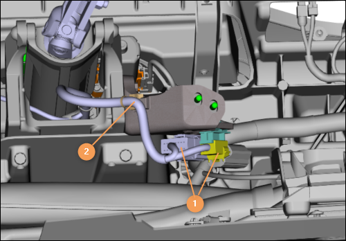
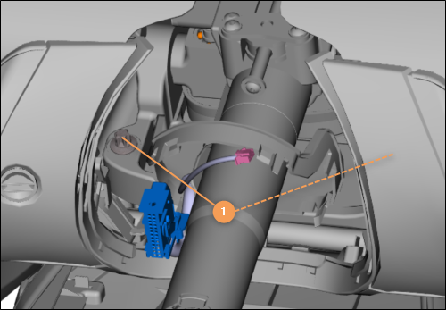
| | | 1. | Disconnect the electrical connectors (1).
Disengage the clip (2).
| | | 
|
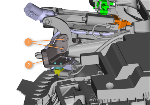
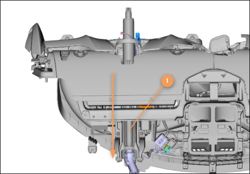
| 2. | Move the bracket (2) to the side.
| | | 
|
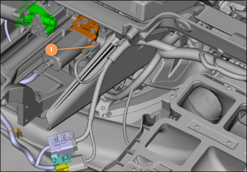
| 3. | Disconnect the electrical connector (1).
| | | 
|
| | | Care Point: | Always replace the bolts. Refer to the Spare Parts Catalogue (SPC) for part numbers.
|
| Care Point: | Refer to the installation procedure for the torque sequence.
|
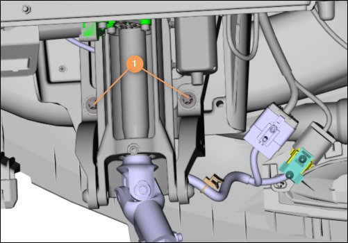
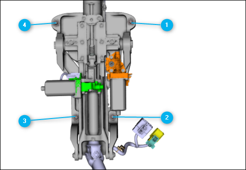
| | | 4. | Remove the bolts (1) and discard.
| | | 
|
| | | Care Point: | Always replace the bolts. Refer to the Spare Parts Catalogue (SPC) for part numbers.
|
| Care Point: | Refer to the installation procedure for the torque sequence.
|
| | | 5. | Remove the bolts (1) and discard.
| | | 
|
| 6. | Remove the upper steering column (1) in the direction shown.
| | | 
|
Install Steering column - Upper - Electric
| | | Care Point: | When you install fixings to the cross car beam you must only install them by hand. Do not use power tools.
|
| Care Point: | Make sure that all bolts fitted are not cross threaded before tightening. Any damage caused to the threads will require the cross car beam to be replaced as no filing, drilling, or tapping can be carried out on the beam.
|
| | | 1. | Install the bolts by hand.
| | | | | Care Point: | Steering column gaiter cannot be fitted until column is extended away from facia.
|
| | | 2. | Install the remaining components in reverse order.
| | | | | Care Point: | The steering column must be calibrated after every installation.
|
| Care Point: | Make sure that the VCI and MDS batteries are in good condition or connected to external power supply.
|
| | | 3. | Connect the McLaren Diagnostic System (MDS).
| | | 4. | Go to Sequences in the Switch control Unit Gateway (SCUG).
| | | | | Care Point: | Make sure any battery chargers are disconnected when performing Steering Column Calibration, either by the MDS sequence or when prompted by the Instrument Cluster.
|
| | | 5. | Carry out Steering Column Calibration sequence.
| | | | | Care Point: | When prompted by the instrument cluster warning.
|
| | | 6. | Using control switch, move steering column to upper and inner most end stops.
| | | 7. | Check the steering column functionality.
| | | 8. | Do a Diagnostic Trouble Code (DTC) read out and clear error memory.
| | | 
|