Preparation work
| 1. | |
| 2. | |
| 3. | Care Point: Remove both sides.
|
| 4. | |
| 5. | |
| 6. | Care Point: Remove both sides.
|
| 7. | Care Point: Remove both sides.
|
| 8. | Care Point: Remove both sides.
|
| 9. | Care Point: Remove both sides.
|
| 10. | Care Point: Remove both sides.
|
| 11. | |
| 12. | |
| 13. | |
| 14. | Care Point: Remove both sides.
|
| 15. | |
| 16. | |
| 17. | |
| 18. | Care Point: Remove both sides.
|
| 19. | |
| 20. | |
| 21. | Care Point: Driver side only.
|
| 22. | Care Point: Remove both sides. Disconnect only.
|
| 23. | Care Point: Remove both sides. Remove wishbone to actuator bolt only.
|
| 24. | |
| 25. | |
| 26. | |
| 27. | |
 WARNING! WARNING!
| |
Possible fluid spills from vehicle systems during repairs or maintenance.
Risk of thermal incidents, slip hazards, corrosion of electrical components, failure of electrical or mechanical components or unwanted odours.
Always limit fluid spills and fully clean the spilled fluid after repairs or maintenance.
| |
Remove Heater hose - HVAC to Engine
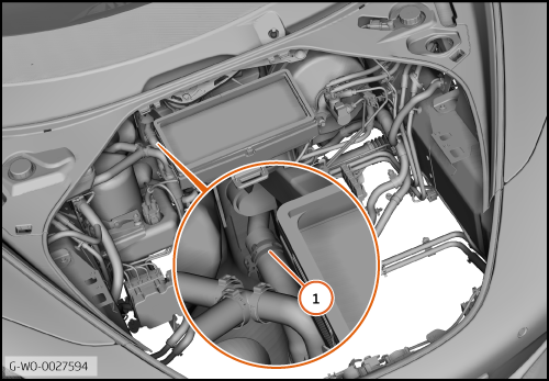
| 1. | Disengage the clip (1) and disconnect the hose.
| | | 
|
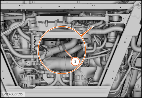
| 2. | Disengage the clip (1) and disconnect the hose.
| | | 
|
| 
|
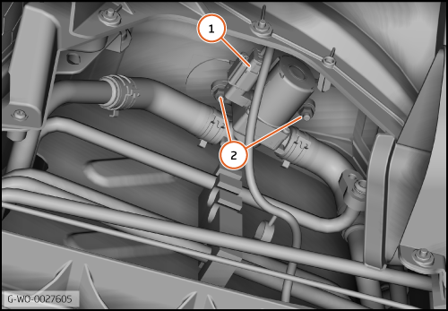
| 4. | Disconnect the electrical connector (1).
Remove the nuts (2) (M6) 8 Nm and disengage the pipe from the studs.
| | | 
|
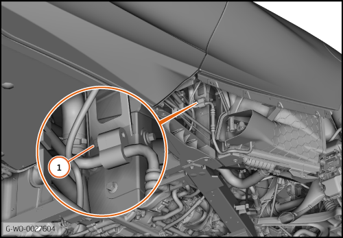
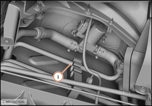
| 5. | Disengage the pipe (1) from the clamp.
| | | 
|
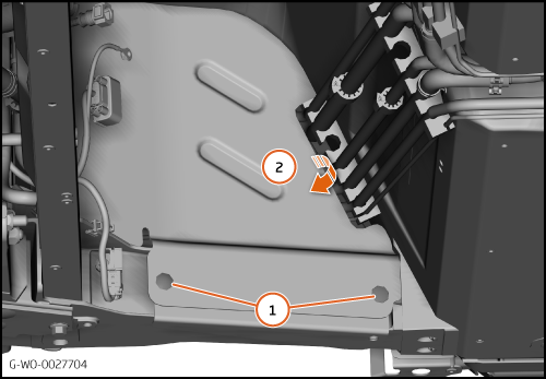
| 6. | Remove the clips (1) and move the heatshield in the direction shown (2).
| | | 
|
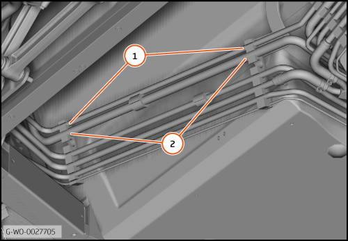
| 7. | Disengage the pipe (1) from the clamps.
Disengage the pipe (2) from the clamps.
| | | 
|
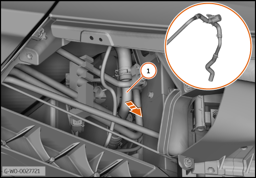
| 8. | Move the pipe (1) in the direction shown to remove it from the engine bay.
| | | 
|
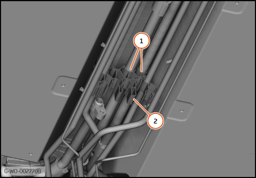
| | | Care Point: | Record the location of the pipes.
|
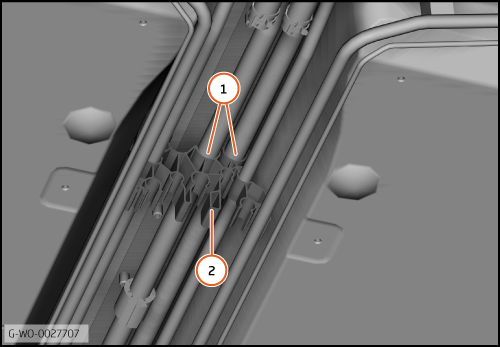
| | | 9. | Disengage the pipes (1) and remove the clamp (2).
| | | 
|
| | | Care Point: | Record the location of the pipes.
|
| | | 10. | Disengage the pipes (1) and remove the clamp (2).
| | | 
|
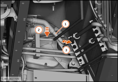
| 11. | Move the pipe (1) in the direction shown (2) then (3).
| | | 
|
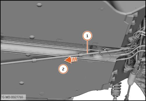
| 12. | Remove the pipe (1) in the direction shown (2).
| | | 
|
Install Heater hose - HVAC to Engine
| 1. | Install the components in reverse order.
| | |