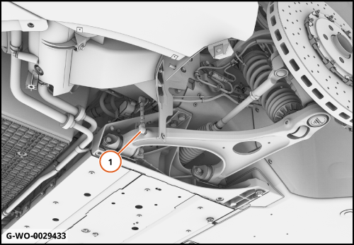
Preparation work
| 1. | |
| 2. | |
| 3. | |
| 4. | Care Point: Disconnect only.
|
Remove Wishbone - Front - Lower
| |
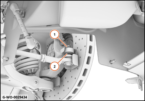
| | | 1. | Release the lock and detach the displacement sensor link rod (1).
| | | 
|
| | | Care Point: | Always replace the ball joint nut. Refer to the Spare Parts Catalogue (SPC) for part numbers.
|
| Care Point: | The ball joint washers are tapered.Make sure that the washer is installed correctly.
|
| Care Point: | Make sure that the track rod heatshield is present and in the correct position.
|
| Care Point: | The use of a ball joint separator tool will aid the next step.
|
| | | 2. | Disengage the ball joint (2).
| | | 
|
| | | Care Point: | Always replace the actuator bolt. Refer to the Spare Parts Catalogue (SPC) for part numbers.
|
| | | 3. | Disengage the actuator (2) from the wishbone (3).
| | | 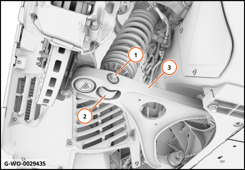
|
| | | Care Point: | Always replace the ball joint nut. Refer to the SPC for part numbers.
|
| Care Point: | The ball joint washers are tapered.Make sure that the washer is installed correctly.
|
| Care Point: | The use of a ball joint separator tool will aid the next step.
|
| | | 4. | Disengage the ball joint (2).
| | | 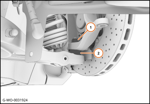
|
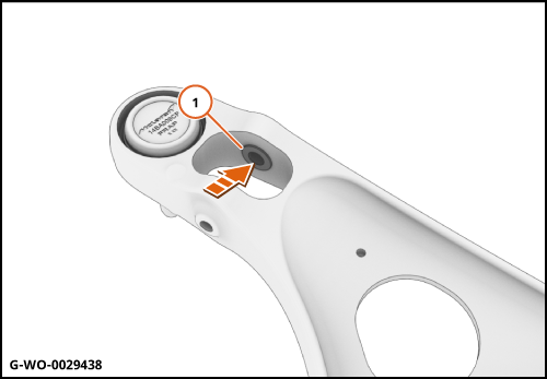
| | | Care Point: | Always replace the wishbone bolts. Refer to the SPC for part numbers.
|
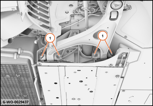
| Care Point: | Torque the bolts (1) in the following order - Outer pair, inner pair.
|
| | | 5. | | | | 6. | Remove the wishbone.
| | | 
|
Install Wishbone - Front - Lower
| | | Care Point: | If you do not install a new wishbone, do the step that follows.
|
| | | 1. | Push the bush (1) a small distance into the wishbone.
| | | | | Care Point: | Make sure that the spacer is fitted between the wishbone and frame.
|
| Care Point: | Check torque of displacement sensor link rod ball studs. 6 Nm.
|
| | | 2. | Install components in reverse order.
| | | 3. | Check the movement of the displacement sensor link rod, ensuring it moves freely.
| | | | | Care Point: | Once vehicle is on the ground.
|
| | | 4. | Apply pressure to top of wheel towards vehicle. If excessive inwards movement of wheel is present, the upper ball joint has failed. This will need to be replaced.
| | | 5. | Connect McLaren Diagnostic System (MDS).
| | | 6. | Proceed to Diagnostic Toolbox
| | | 7. | Select Chassis Control Unit (CCU).
| | | 8. | Access sequences.
| | | 9. | Carry out Damper Sensor Calibration sequence.
| | | | | Care Point: | The procedure below must be claimed separately if you make a warranty claim.
|
| | | 10. | Make sure that the suspension geometry is in tolerance.
| | | 
|