| | | Care Point: | For the steps that follow, refer to the applicable procedures for the fastener locations and torque values.
|
| | | 1. | Remove the engine.
| | | 2. | Remove the crank case ventilation (CCV) breather system.
| | | 3. | Remove the intake manifold assembly.
| | | 4. | Remove the ignition coils.
| | | 5. | Remove the spark plugs.
| | | 6. | Remove the sensors - Cam phaser.
| | | 7. | Remove the camshaft cover.
| | | 8. | Remove cam phaser - Right.
| | | 9. | Remove cam phaser - Left.
| | | 10. | Remove the front cover.
| | | 11. | Remove the chain drive kit - Camshaft.
| | |
|
| | | Care Point: | It is not permitted for any unwanted material to enter the oil galleries.
|
| Care Point: | The front camshaft bearing cap must be removed first.
|
| Care Point: | The camshaft bearing caps must be installed to their initial location and the arrow marks must point to the front of the engine.
|
| Care Point: | Make sure that you record the location of the camshaft bearing caps.
|
| Care Point: | To prevent damage to the camshafts, they must be set to the correct position before you remove the bearing bolts.
|
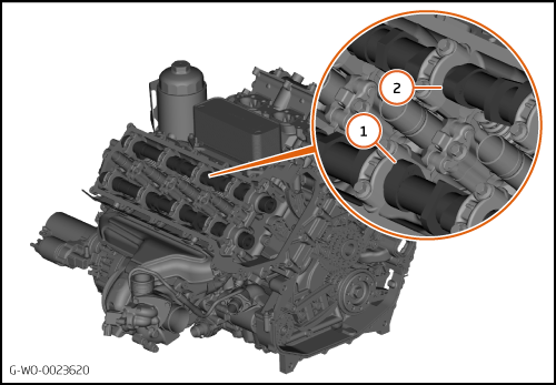
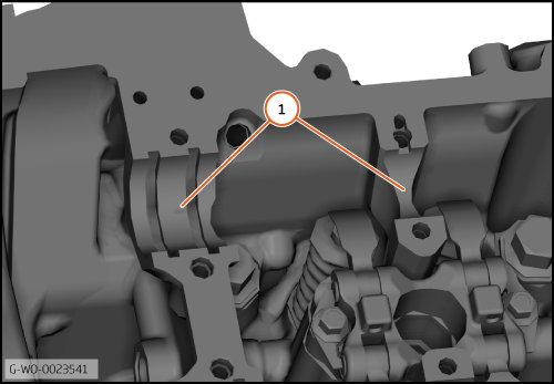
| | | 12. | Set the right-hand cylinder 2 exhaust camshaft lobes to the 1 o'clock position (1).
| | | 13. | Set the right-hand cylinder 2 inlet camshaft lobes to the 111 o'clock position (2).
| | | 
|
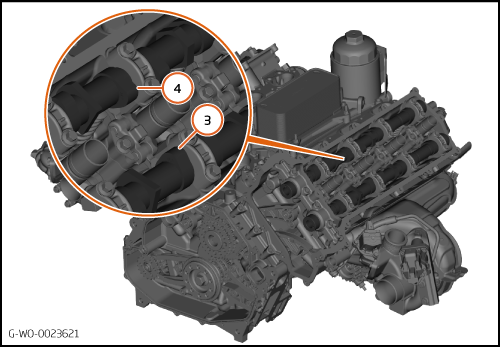
| 14. | Set the left-hand cylinder 6 exhaust camshaft lobes to the 11 o'clock position (3).
| | | 15. | Set the left-hand cylinder 6 inlet camshaft lobes to the 1 o'clock position (4).
| | | 
|
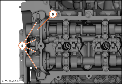
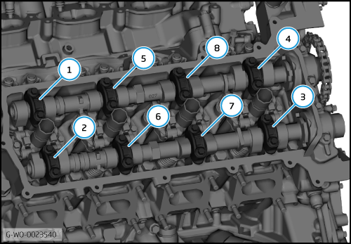
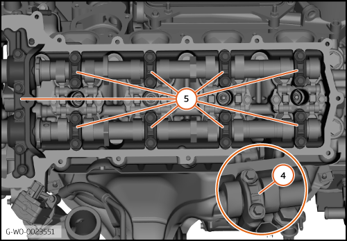
| | | | | 16. | Remove the bolts (5). Refer to the installation section for the torque sequence.
| | | 17. | Remove the front camshaft bearing cap (6).
| | | 
|
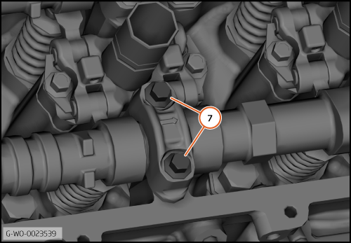
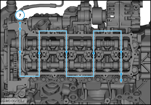
| | | | | 18. | The illustration shows the camshaft bearing cap bolts (7).
| | | 
|
| | | | | 19. | Remove the bearing cap bolts and the bearing caps in sequence (1 to 8).
| | | 20. | Remove the camshafts.
| | | 
|
| 
|
| | | Care Point: | The camshafts have marks to aid location. Make sure that you install the camshafts to the correct location.
|
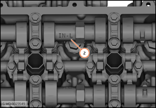
| | | 2. | The illustration shows the left side inlet camshaft marks (2).
EX L = Exhaust left
IN R = Inlet right
EX R = Exhaust right
| | | 3. | Install the camshafts to the cylinder head.
| | | 
|
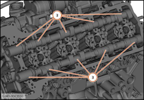
| 4. | Apply a small quantity of EP 80 Hypoid oil to the top of the camshaft bearing journals (3).
| | | 
|
| | | Care Point: | Make sure that you install the camshaft bearing caps to the correct location.
|
| Care Point: | When you install the camshaft bearing caps, make sure that the arrows (4) point to the front of the engine.
|
| | | 5. | Install the camshaft bearing caps (5). Tighten the bolts with your fingers.
| | | 
|
| | | Care Point: | If you do not obey the torque sequence, damage to the camshaft bearing caps can occur.
|
| | | 6. | Tighten the camshaft bearing cap bolts in the sequence shown (6) (M6x20) 5 Nm.
| | | 
|
| 7. | Tighten the camshaft bearing cap bolts in the sequence shown (7) (M6x20) 10 Nm.
| | | 8. | Install the chain drive kit - Camshaft.
| | | | | Care Point: | Make sure that the engine timing is correct.
|
| | | 9. | | | | 10. | Install the remaining components in reverse order.
| | | 
|