Repair instructions
    Body Structures
    Body Panels and Closures
    Body Exterior
    Chassis
    Powertrain
      Heat Insulation
      Engine
        Power Unit Service Procedures
        Power Unit
          DA-RM-05F001-01-001 - Remove/Install engine
          DA-RM-05F001-01-002 - Remove/Install front cover
          DA-RM-05F001-01-003 - Remove/Install NVH - Front Cover
          DA-RM-05F001-01-004 - Remove/Install perimeter seal - Front cover
          DA-RM-05F001-01-005 - Remove/Install seal - Crank - Front
          DA-RM-05F001-01-006 - Remove/Install seal - Crank - Rear
          DA-RM-05F001-01-007 - Remove/Install cylinder head assembly
          DA-RM-05F001-01-008 - Remove/Install camshaft cover - Left
          DA-RM-05F001-01-009 - Remove/Install camshaft cover - Right
          DA-RM-05F001-01-010 - Remove/Install chain drive kit - Camshaft
          DA-RM-05F001-01-011 - Remove/Install cam phaser - Left
          DA-RM-05F001-01-012 - Remove/Install cam phaser - Right
          DA-RM-05F001-01-013 - Remove/Install solenoid - Cam phaser - Exhaust
          DA-RM-05F001-01-014 - Remove/Install solenoid - Cam phaser - Inlet
          DA-RM-05F001-01-015 - Remove/Install sensor - Cam phaser
          DA-RM-05F001-01-016 - Remove/Install sensor - Cylinder head temperature
          DA-RM-05F001-01-017 - Remove/Install pressure switch - Oil
          DA-RM-05F001-01-018 - Remove/Install crankshaft damper
          DA-RM-05F001-01-019 - Remove/Install sensor - Crank position
          DA-RM-05F001-01-020 - Remove/Install sensor - Knock
          DA-RM-05F001-01-021 - Remove/Install thermostat assembly
          DA-RM-05F001-01-022 - Remove/Install hose - Degas
          DA-RM-05F001-01-023 - Remove/Install Assembly - Turbocharger
          DA-RM-05F001-01-024 - Remove/Install wastegate assembly - Turbo charger
          DA-RM-05F001-01-025 - Remove/Install dump valve
          DA-RM-05F001-01-026 - Remove/Install fuel rail
          DA-RM-05F001-01-027 - Remove/Install injector - Fuel rail
          DA-RM-05F001-01-028 - Remove/Install Intake manifold assembly
          DA-RM-05F001-01-029 - Remove/Install sensor - Temperature manifold absolute pressure (TMAP) - Intake
          DA-RM-05F001-01-030 - Remove/Install throttle body - Air intake
          DA-RM-05F001-01-031 - Remove/Install crank case ventilation (CCV) breather system
          DA-RM-05F001-01-032 - Remove/Install harness - Engine
          DA-RM-05F001-01-033- Remove/Install spark plug
          DA-RM-05F001-01-034 - Remove/Install Ignition coil
          DA-RM-05F001-01-035 - Remove/Install exhaust manifold
          DA-RM-05F001-01-036 - Remove/Install Hose - Water feed - Turbo
          GI-RM-0003 - Remove/Install Rocker mounting bracket
          GI-RM-0004 - Remove/Install Valve - Cylinder head
          GI-RM-0005 - Remove/Install Oil seal - Valve stem
          GI-RM-0006 - Remove/Install Ladderframe
          GI-RM-0007 - Remove/Install Camshafts
        Engine Control Unit
        Secondary Air System
      Engine Air Systems
      Engine Oil System
      Engine Cooling System
      Engine Ancillaries
      Engine Mounting
      Transmission
      Transmission Cooling System
      Transmission Mounting
      Driveshafts
      Exhaust
    Electrical
    Interior
    Accessories
    PDI/Service/Track/Technical Sheets
    Paint Technical Data Sheets
    Wiring Schematics
  Customer Service
       Special advice          Tools/Equipment           Fluids, lubricants, adhesive   
Instructions
Powertrain / Engine / Power Unit / GI-RM-0003 - Remove/Install Rocker mounting bracket
Remove Rocker mounting bracket
 
Care Point:
For the steps that follow, refer to the applicable procedures for the fastener locations and torque values.

 
1.  
Remove the engine.
 
2.  
Remove the transmission from the engine.
 
3.  
Remove the engine from the engine cradle.
 
 
Care Point:
Make sure that you use a suitable engine stand.

 
4.  
Install the engine to an engine stand.
 
5.  
Remove the cylinder head.


Care Point:
Put the cylinder head on a cylinder head stand.

Care Point:
Refer to the installation section for the torque sequence.

Care Point:
Risk of damage. Make sure that unwanted objects do not fall into the oil galleries.
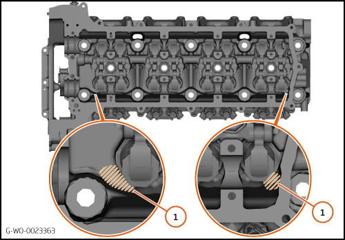
 
6.  
Install plugs to make sure that unwanted objects do not go into the oil galleries (1).
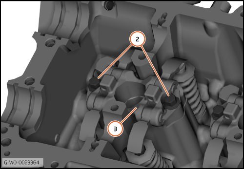


7.  
Remove the bolts (2).
 
 
Care Point:
Risk of damage. Do not cause damage to the cam cover seal mating face.
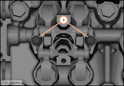
 
8.  
Remove the rocker mounting bracket (3).


Install Rocker mounting bracket
 
Care Point:
Make sure that you install the rocker mounting bracket correctly.

 
1.  
Install the rocker mounting bracket.
 
2.  
Loosely install the bolts.


Care Point:
Use a 0.15mm feeler gauge in the step that follows.
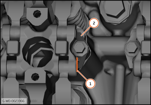
 
3.  
Insert the feeler gauge as shown (1) to make sure the washer retainer (2) is correctly aligned.


Care Point:
Keep the feeler gauge in position when you tighten the bolts.

 
4.  
Torque the bolts (3) (M6x30) 5 Nm.
 
5.  
Torque the bolts (3) (M6x30) 10 Nm.
 
6.  
Install the cylinder head to the cylinder block.
 
7.  
Do the valve clearance adjustment procedure. Refer to GI-RM-0002 - Valve clearance adjustment.
 
8.  
Install the remaining components in reverse order.


   Note