Remove Valve - Cylinder head
| | | Care Point: | For the steps that follow, refer to the applicable procedures for the fastener locations and torque values.
|
| | | 1. | Remove the engine.
| | | 2. | Remove the transmission from the engine.
| | | 3. | Remove the engine from the engine cradle.
| | | | | Care Point: | Make sure that you use a suitable engine stand.
|
| | | 4. | Install the engine to an engine stand.
| | | 5. | Remove the cylinder head.
| | | 6. | | | |
|
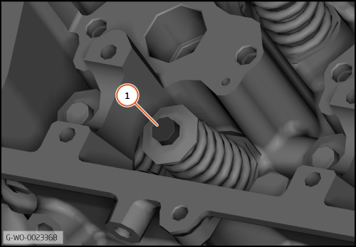
| | | Care Point: | Make sure that the valve shim does not fall into an oil gallery.
|
| Care Point: | Make sure that you record the location of the valve shim.
|
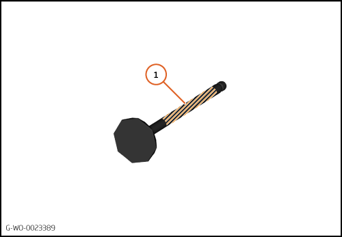
| | | 7. | Remove the valve shim (1).
| | | 
|
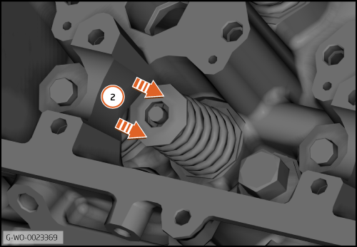
| | | Care Point: | Use a valve spring compression tool.
|
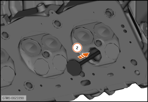
| | | 8. | Compress the valve spring (2).
| | | 
|
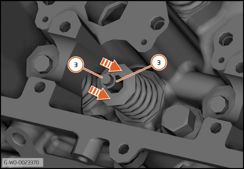
| | | Care Point: | Make sure that the collets do not fall into an oil gallery.
|
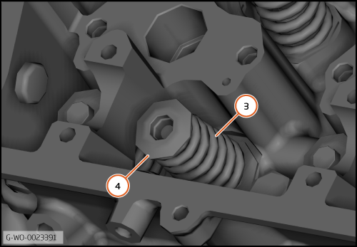
| | | 9. | While the valve spring is compressed, remove the collets (3).
| | | 10. | Decompress the valve spring and remove the valve spring compression tool.
| | | 
|
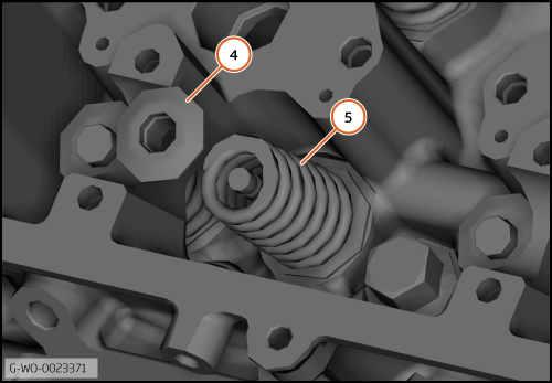
| | | Care Point: | Always replace the valve cap and collets. Refer to the Spare Parts Catalogue (SPC) for part numbers.
|
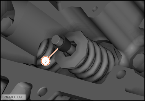
| Care Point: | Make sure that you record the location of the valve spring.
|
| | | 11. | Remove the valve cap (4) and the valve spring (5).
| | | 
|
| | | Care Point: | Make sure that you record the location of the valve.
|
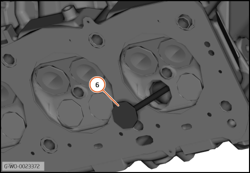
| | | 12. | Remove the valve (6).
| | | 
|
Install Valve - Cylinder head
| | | Care Point: | If the valve stem has scores, replace it.
|
| | | 1. | Lap the valve to the valve seat.
| | | | | Care Point: | Make sure that you remove any remaining valve grinding paste.
|
| | | 2. | Make sure that the valve is clean and dry.
| | | 3. | | | |
|
| 
|
| 5. | Install the valve to the cylinder head (2).
| | | 
|
| | | Care Point: | Do not let the valve fall.
|
| | | 6. | Install the valve spring (3) and valve cap (4) to the cylinder head.
| | | 
|
| | | Care Point: | Make sure that the valve spring is installed correctly.
|
| Care Point: | Use a valve spring compression tool.
|
| | | 7. | Compress the valve spring and install the collets (5).
| | | | | Care Point: | Make sure that the collets are installed correctly.
|
| | | 8. | Decompress the valve spring and remove the compression tool.
| | | | | Care Point: | Do the next step to confirm that the valve and collets are installed correctly.
|
| | | 9. | Use a nylon drift and a hammer to lightly hit the top end of the valve.
| | | 10. | Install the remaining cylinder head components in reverse order.
| | | 11. | Install the cylinder head to the cylinder block.
| | | | | | | 12. | | | | | | Care Point: | Make sure that any plugs you have installed are removed from the cylinder head.
|
| | | 13. | Install the remaining components in reverse order.
| | | 
|