| | | Care Point: | For the steps that follow, refer to the applicable procedures for the fastener locations and torque values.
|
| | | 1. | Remove the engine.
| | | 2. | Remove the transmission from the engine.
| | | 3. | Remove the engine from the engine cradle.
| | | | | Care Point: | Make sure that you use a suitable engine stand.
|
| | | 4. | Install the engine to an engine stand.
| | | 5. | Remove the crankshaft damper.
| | | 6. | Remove the front cover. Replace the front crankshaft seal.
| | | 7. | Remove the driveline damper.
| | | 8. | Remove the rear crankshaft seal. Replace the rear crankshaft seal.
| | | 9. | Remove the Heating, Ventilation and Air Conditioning (HVAC) compressor.
| | | 10. | Remove the water pump. Replace the gasket.
| | | 11. | Remove the alternator.
| | | 12. | Remove the oil pump. Replace the gasket.
| | | 13. | Remove the crankshaft position sensor.
| | |
|
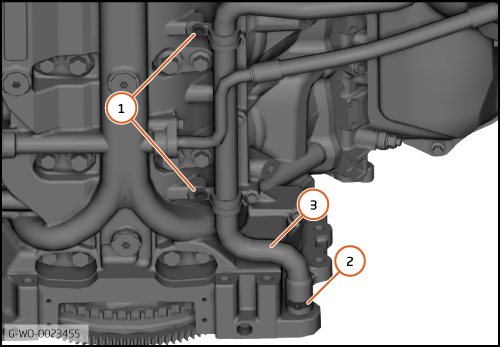
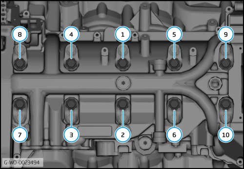
| 14. | | | | 15. | Remove the clip (2) and remove the hose (3).
| | | 
|
| 16. | | | | 17. | Disconnect the hoses (5) and drain the remaining oil.
| | | 
|
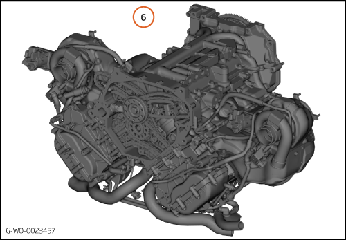
| 18. | Turn the engine 180° on the engine stand (6).
| | | 
|
| | | Care Point: | If tension pins are not available, use a heat-treated pin with a diameter of 3mm.
|
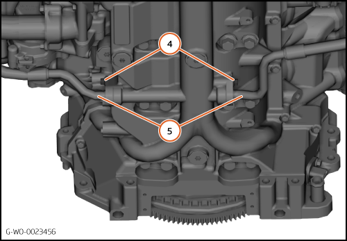
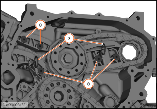
| | | 19. | Install the chain guide tension pins (7).
| | | 20. | Remove the bolts (8) (M6x16) 10 Nm and remove the tension guides.
| | | 
|
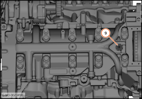
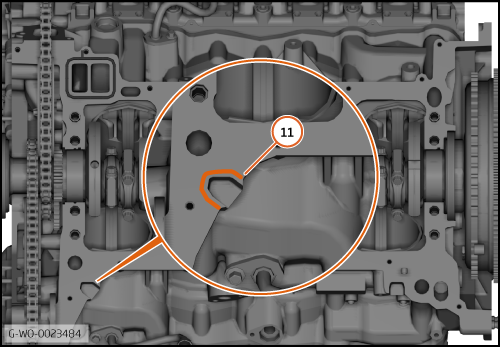
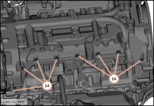
| 21. | Remove the crankshaft timing plug (9) 20 Nm.
| | | 
|
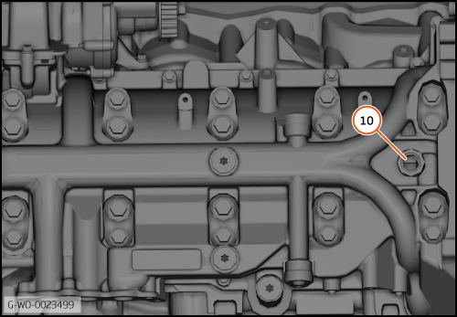
| 22. | Turn the crankshaft clockwise until you can visually confirm it is in the safe position (10).
| | | 
|
| | | Care Point: | Do not let the crankshaft turn after this step.
|
| | | 23. | | | | 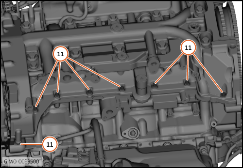
|
| 
|
| | | Care Point: | Always replace the main bearing bolts and washers. Refer to the Spare Parts Catalogue (SPC) for part numbers.
|
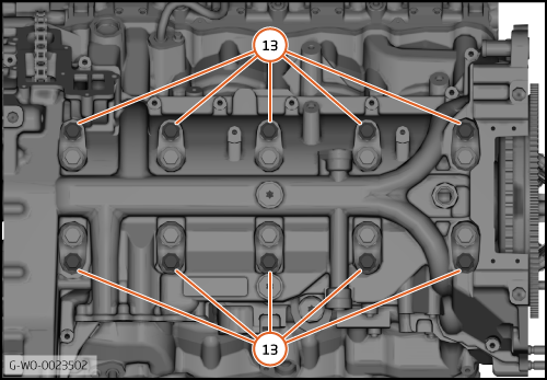
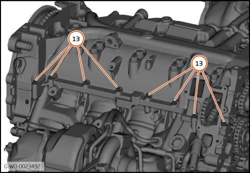
| | | 25. | Remove the bolts (13). Refer to the installation section for the torque sequence.
| | | 
|
| | | Care Point: | Make sure that the crankshaft does not turn.
|
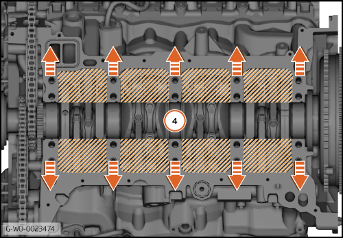
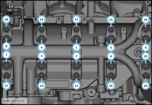
| | | 26. | Loosen the bolts 180° in sequence (1 to 10).
| | | 27. | Remove the bolts in sequence (1 to 10).
| | | | | Care Point: | Make sure that the crankshaft bearings do not move in the step that follows.
|
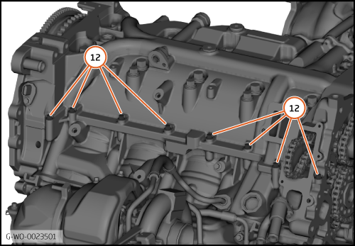
| | | 28. | Carefully remove the ladderframe.
| | | 
|
| | | Care Point: | Always replace the seals after you have cleaned the cylinder block. Refer to the Spare Parts Catalogue (SPC) for part numbers.
|
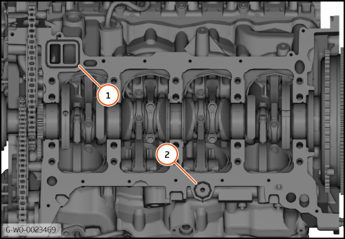
| | | 1. | Remove the water passage seal (1) and the cold start oil seal (2).
| | | 
|
| | | Care Point: | Make sure that unwanted material does not go into the engine.
|
| Care Point: | Make sure that you use cloth that does not cause dust or particles to enter the engine.
|
| | | 2. | Carefully install cloth around the inner of the cylinder block (3).
| | | 
|
| | | Care Point: | It is not permitted for any unwanted sealant to enter the engine.
|
| Care Point: | It is not permitted for any unwanted sealant to enter the oil galleries.
|
| Care Point: | You must only remove the old sealant in the direction shown.
|
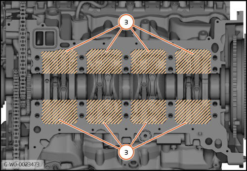
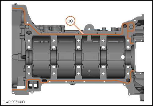
| | | 3. | Carefully remove the old sealant from the cylinder block mating surface in the direction shown (4).
| | | | | | | 4. | | | | 5. | Clean any unwanted material from the cylinder block mating surface. Use BETACLEAN 3900.
| | | 6. | Remove the tissue paper from the cylinder block.
| | | 
|
| | | Care Point: | It is not permitted for any unwanted material to enter the oil galleries.
|
| Care Point: | You must only remove the old sealant in the direction shown.
|
| | | 7. | Carefully remove the old sealant from the ladderframe in the direction shown (5).
| | | 8. | | | | | | Care Point: | The ladderframe must be fully clean and dry.
|
| | | 9. | Clean any unwanted material from the ladderframe mating surface. Use BETACLEAN 3900.
| | | 
|
| | | Care Point: | Do the steps that follow before you apply sealant to the ladderframe.
|
| | | 10. | | | | | | Care Point: | Make sure you apply the lubricant smoothly.
|
| | | 11. | | | | 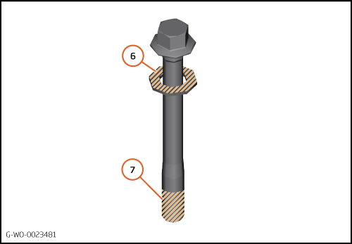
|
| 12. | Install the new water passage seal (8) and the new cold start oil seal (9).
| | | 
|
| | | Care Point: | Do not let sealant go into the engine or oil galleries.
|
| Care Point: | After you apply the sealant, the ladderframe must be installed in less than 20 minutes.
|
| Care Point: | The correct bead diameter is 2.5mm.
|
| | | 13. | Carefully apply a bead of sealant to the ladderframe as shown (10). Use Threebond 1217F.
| | | 
|
| | | | | 14. | Carefully apply a bead of sealant to the cylinder block as shown (11). Use Threebond 1217F.
| | | | | Care Point: | Make sure that you align the ladderframe correctly to the cylinder block.
|
| | | 15. | Carefully install the ladderframe to the cylinder block dowels.
| | | 
|
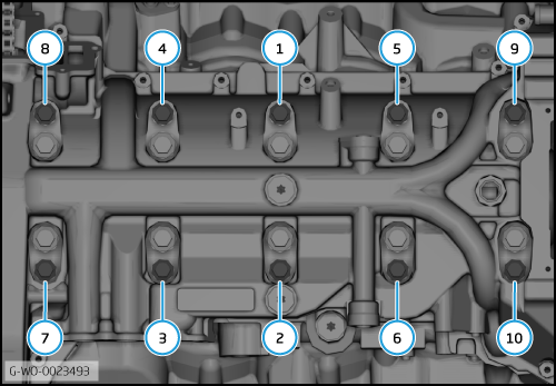
| 16. | Install the bolts (12). Tighten the bolts with your fingers.
| | | 
|
| 17. | Install the bolts (13). Tighten the bolts with your fingers.
| | | 
|
| | First ladderframe torque sequence
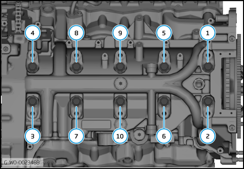
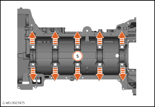
| | | 18. | Torque the bolts in sequence (1 to 20) 20 Nm.
| | | 19. | Do the torque sequence again.
| | | 
|
| | Second ladderframe torque sequence
| | | 20. | | | | 21. | Do the torque sequence again.
| | | 
|
| 22. | | | | 23. | Do the torque sequence again.
| | | 
|
| | Final ladderframe torque sequence
| | | 24. | | | | 25. | Do the torque sequence again.
| | |
|
| 
|
| 
|
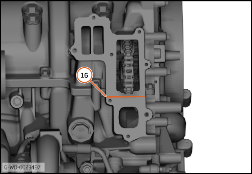
| 28. | Remove any unwanted sealant from the water pump mating face (16).
| | | 29. | Install the remaining components in reverse order.
| | | 
|