Preparation work
Remove Breather
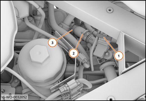
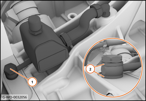
| 1. | Disconnect the electrical connector (1).
Disengage the clip (2).
Disconnect the secondary air hose (3) and move aside.
| | | 
|
| | | Care Point: | Risk of damage. Clean away any spilt fluid before the step that follows.
|
| Care Point: | The use of a heat gun will be required to remove the press fit clutch oil breather.
|
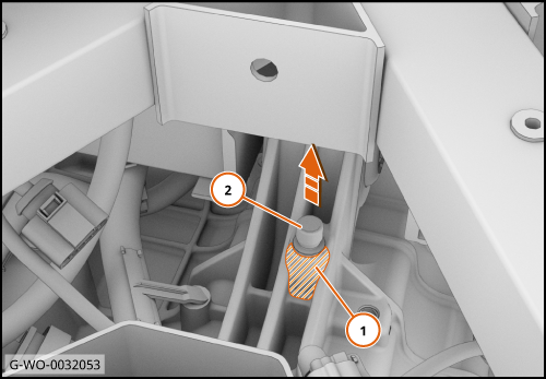
| | | 2. | Heat the area shown (1) to help release the breather.
Use a pair of pliers to remove the breather (2) and discard.
| | | 
|
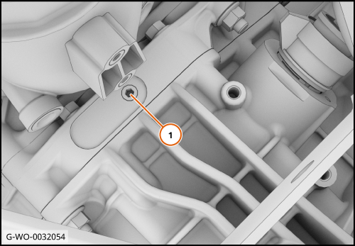
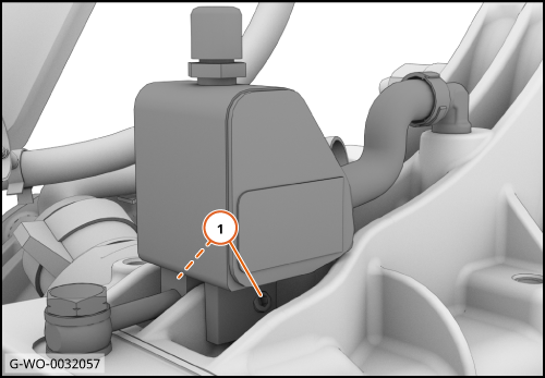
| 3. | Remove the grub screw (1) and discard.
| | | 
|
Install Catch tank - Clutch oil - DCT
| | | Care Point: | The use of a heat gun will be required to install the press fit 90° hose fitting.
|
| Care Point: | The 90° hose fitting is an interference fit and will need to be pressed in to place.
|
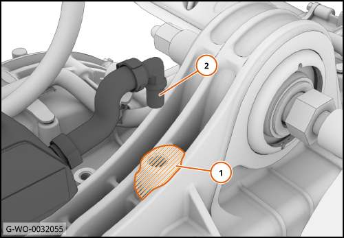
| | | 1. | Apply heat to the area shown (1).
Install the 90° hose fitting (2).
| | | 
|
| | | Care Point: | Makes sure that the washers (2) are fitted.
|
| | | 2. | Install the banjo bolt (1) 15 Nm.
| | | 
|
| 3. | Tighten the grub screws (1) 2.5 Nm.
| | | 
|
| | | Care Point: | Make sure that the hose does not clash with the catch tank assembly.
|
| Care Point: | Make sure that the engine harness does not clash with the catch tank assembly.
|
| | | 4. | Connect the hose (1).
Engage the clip (2).
Connect the electrical connector (3).
| | | 5. | Install the remaining components in reverse order.
| | | 
|