Preparation work
| 1. | |
| 2. | |
| 3. | |
| 4. | |
| 5. | Care Point: Remove both sides.
|
| 6. | Care Point: Remove both sides.
|
| 7. | |
| 8. | |
| 9. | |
| 10. | Care Point: Remove both sides.
|
 WARNING! WARNING!
| |
Possible fluid spills from vehicle systems during repairs or maintenance.
Risk of thermal incidents, slip hazards, corrosion of electrical components, failure of electrical or mechanical components or unwanted odours.
Always limit fluid spills and fully clean the spilled fluid after repairs or maintenance.
| |
Pressure test engine air system
| | | Care Point: | The following procedure must only be carried out with the engine at room temperature.
|
| Care Point: | Make sure that the oil filler cap has been fitted correctly.
|
| Care Point: | Engine may smoke after pressure test procedure has been carried out on initial start up.
|
| Care Point: | Use suitable container to catch excess fluid.
|
| | | 1. | | | | 
|
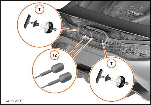
| | | Care Point: | Insert expanding plug as far down the muffler tip as possible.
|
| | | 2. | Fit expanding blanks (T2) and blanks (T) to exhaust muffler tips.
| | | 
|
| 3. | Connect expanding blank line (T3) to pressure tester.
| | | 4. | Connect air line (P) to pressure tester (T4).
| | | 
|
| | | Care Point: | Set pressure regulator for exhaust muffler tip blank valve at 0 before opening valve. Once valve is open, adjust until a pressure of 1.5 bar has been achieved (T7).
Do not exceed 1.5 bar pressure when expanding the exhaust muffler tip blank.
Do not expand the exhaust muffler tip plugs when not fitted to the vehicle.
Make sure that the exhaust muffler tip blank valve lever 2 (T5) is closed (B) when expanding the exhaust muffler tip blanks. Once test is complete open lever 2 (T5, A) to release pressure and allow the muffler tip expanding plugs to be removed.
Exhaust muffler tip blanks must be fitted and expanded at the same time.
|
| | | 5. | Open exhaust muffler tip blank valve (T6) to position (D) to expand exhaust muffler tip blank.
| | | 6. | Close exhaust muffler tip blank valve (T6) to position ©) once exhaust muffler tip blank has reached optimum size.
| | | 
|
| | | Care Point: | Brake boost hose must be blanked to prevent pressurising the brake system.
|
| | | 7. | Clamp brake boost hose using generic hose clamp (2).
| | | 
|
| 8. | Fit purge hose valve connection to purge spigot (3).
| | | 
|
| | | Care Point: | Set pressure regulator for purge hose valve to 0 before opening valve. Once open, adjust until a pressure of 0.35 has been achieved (T9).
Do not exceed 0.35 bar pressure in the system.
|
| | | 9. | Open purge hose valve (T8) to position (E) to introduce pressure to the system to allow a pressure test to be carried out.
| | | 10. | Maintain 0.35 bar pressure for 30 seconds and listen for audible leaks.
| | | | | Care Point: | Pressure will reduce gradually over the 30 second time period. This is an acceptable condition to experience.
The pressure drop can be monitored using the second gauge (T10).
|
| | | 11. | Close purge hose valve (T8) to position (F), and hold pressure within system for minimum of 30 seconds.
| | | 12. | Continue to listen for audible leaks.
| | | 13. | If any leaks are sourced, fix immediately.
| | | | | Care Point: | Leakage will occur around the wastegate shaft where it exits the turbine housing and from the dump valve top bolt (3). Leakage will also occur at the dump valve capsule (4). This is a normal condition and leakage from here is allowed if it is less then 0.2 litres per minute.
|
| | | 14. | Repeat steps 12 - 14 until all leaks no longer exist.
| | | 15. | Carry out oil fill procedure.
| | | 16. | | | | 17. | Install components in reverse order.
| | | 
|