Preparation work
| 1. | Care Point: You must attach a copy of any Diagnostic Trouble Codes (DTC's) to the work package before and after you install the shift paddles.
|
| 2. | |
| 3. | |
| 4. | |
Remove standard shift paddles
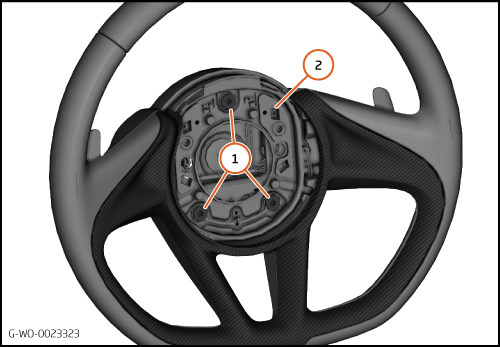
| 1. | Remove the bolts (1) 5 Nm and remove the airbag carrier (2).
| | | 
|
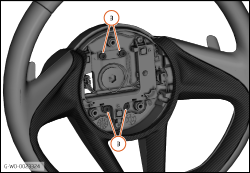
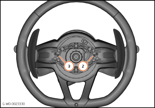
| 2. | Remove the bolts (3) 5 Nm and remove the shift paddles.
| | | 
|
Install extended shift paddles
| | | Care Point: | Do not touch the switches.
|
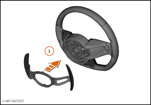
| | | 1. | Install the extended shift paddles to the steering wheel (1).
| | | 
|
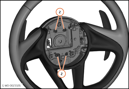
| 2. | Tighten the bolts (2) 5 Nm.
| | | 
|
| 3. | Make sure that the springs (3) are located correctly.
| | | 
|
| 4. | Install the airbag carrier (4) to the steering wheel.
| | | 5. | Tighten the bolts (5) 5 Nm.
| | | 
|
Calibrate extended shift paddles
| 1. | Connect the 12V battery.
| | | 2. | Connect the McLaren Diagnostic System (MDS).
| | |
|
| | | Care Point: | Risk of damage. Be careful with easily damaged parts and trim.
|
| Care Point: | Do not damage the wiring harness in the steps that follow.
|
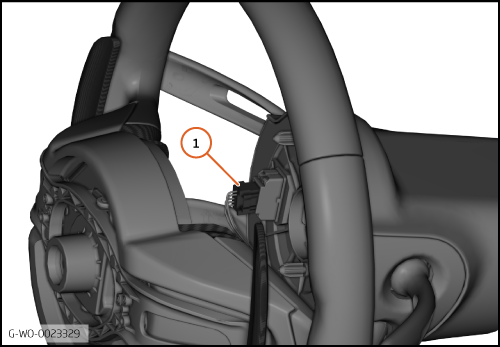
| Care Point: | Do not let the steering wheel fall when the electrical connector is connected.
|
| | | 3. | Reverse the steering wheel and install the electrical connector (1).
| | | | | Care Point: | The shift paddles must be calibrated to operate correctly.
|
| | | 4. | Go to the Transmission Control Unit (TCU).
| | | | | | | 5. | Go to Actual values.
| | | 6. | Go to All actual values.
| | | 7. | Select Voltage downshift switch and Voltage upshift switch.
| | | 8. | Press the calculator button to increase the display size.
| | | 
|
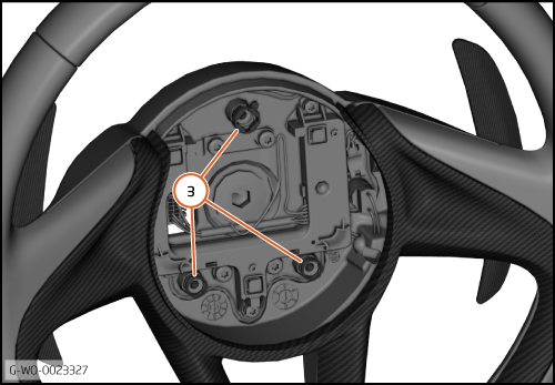
| 9. | The illustration shows the inner adjustment screws for down-shift (2) and up-shift (3).
| | | 10. | Down-shift paddle inner screw adjustment:
Turn the inner screw clockwise until the paddle does not click when pressed.
| | | 11. | Push and hold the down-shift paddle.
| | | 12. | Slowly turn the inner screw counterclockwise.
| | | 13. | Monitor the down-shift voltage on the MDS screen.
| | | 14. | Stop the adjustment when the voltage falls to approximately 1.6v or less.
| | | 15. | Release the down-shift paddle.
| | | 16. | Turn the inner screw counterclockwise 3 turns.
| | | 17. | Do steps 10 to 16 for the up-shift paddle.
| | | 
|
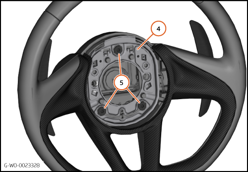
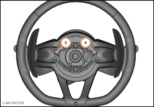
| 18. | The illustration shows the outer adjustment screws for down-shift (4) and up-shift (5).
| | | 19. | Down-shift paddle outer screw adjustment:
Monitor the down-shift voltage on the MDS screen
| | | 20. | Slowly turn the outer screw clockwise.
| | | 21. | Stop the adjustment when the voltage falls to approximately 2.5v.
| | | 22. | Turn the outer screw counterclockwise 1.5 turns.
| | | 23. | Do steps 19 to 22 for the up-shift paddle.
| | | 24. | End the MDS session and disconnect the 12V battery.
| | | 25. | Install the remaining components in reverse order.
| | | 26. | Do a road test to confirm that the system operates correctly.
| | | 27. | Connect MDS and do a DTC read and clear after you attach a copy of any DTC's to the work package.
| | | 
|