Preparation work
 WARNING! WARNING!
| |
Risk of injury and poisoning working with hydraulic fluid!
Risk of injury to skin or eyes from hydraulic fluid spraying out under pressure. When disengaging hydraulic lines without depressurising the system, dangerous skin or eye injuries can occur due to the very high pressures (in excess of 200 bar). If hydraulic fluid, particularly central hydraulic fluid (especially harmful), comes into contact with unprotected skin, this can cause damage to the skin.
If hydraulic fluid is swallowed, this can lead to poisoning symptoms such as headache, dizziness, nausea, vomiting, diarrhoea, cramps and unconsciousness.
Wear protective gloves, protective clothing and eye protection.
| • | Depressurise and drain the system if necessary when commencing work on hydraulic systems.
| | • | Never put hydraulic fluid into beverage containers.
| | • | Ensure sufficient ventilation, especially in the case of central hydraulic fluid.
| | • | Ensure that only authorised persons have access to hydraulic fluid.
| | • | Immediately seal disconnected leads and hoses and the connections to the assembly with blind plugs.
|
| |
WARNING!
| |
Risk of injury and poisoning working with hydraulic fluid under pressure!
Risk of injury to skin or eyes from hydraulic fluid spraying out under pressure. If any part of the hydraulic circuit has failed, a possibility of the system not depressurising can occur. Extra precaution is required in this event. If hydraulic fluid is swallowed, this can lead to poisoning symptoms such as headache, dizziness, nausea, vomiting, diarrhoea, cramps and unconsciousness.
Always wear skin protection cream, protective gloves and safety glasses when working on a potentially pressurised system.
| |
WARNING!
| |
Possible fluid spills from vehicle systems during repairs or maintenance.
Risk of thermal incidents, slip hazards, corrosion of electrical components, failure of electrical or mechanical components or unwanted odours.
Always limit fluid spills and fully clean the spilled fluid after repairs or maintenance.
| |
Remove Membrane type accumulator or metal bellows type accumulator - Front
| | | | | 1. | Refer to the table below for information on which procedure you must follow.
FAULT
| PARTS TO INSTALL
| SOFTWARE TO INSTALL
|
1 or more membrane type accumulators failed
| Replace all 4 membrane type accumulators with 4 metal bellows type accumulators. Always use the new clearance bolts.
| Metal bellows type accumulator software update
| Actuator failed (membrane type accumulator) - accumulator OK
| | None
| Actuator failed (membrane type accumulator) - accumulator failed
| Replace the failed actuator (membrane type accumulator) with a new actuator (metal bellows type accumulator). Refer to DA-RM-04B001-01-001 - Remove/Install actuator - Front. Replace the remaining membrane type accumulators with metal bellows type accumulators. Always use the new clearance bolts.
| Metal bellows type accumulator software update
| Metal bellows type accumulator failure
| Replace the failed metal bellows type accumulator with a new metal bellows type accumulator
| None
| Actuator failed (metal bellows type accumulator) - accumulator OK
| | None
|
| | |
|
| | | Care Point: | This procedure gives the instructions to remove a membrane type accumulator, and install a new metal bellows type accumulator.
|
| Care Point: | The procedure is the same when you remove a metal bellow type accumulator and install a new metal bellows type accumulator.
|
| Care Point: | You must have the aid of one more person when you do this procedure.
|
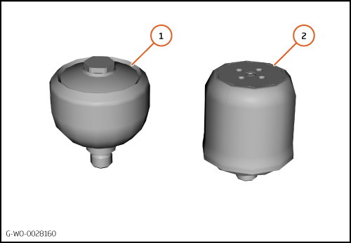
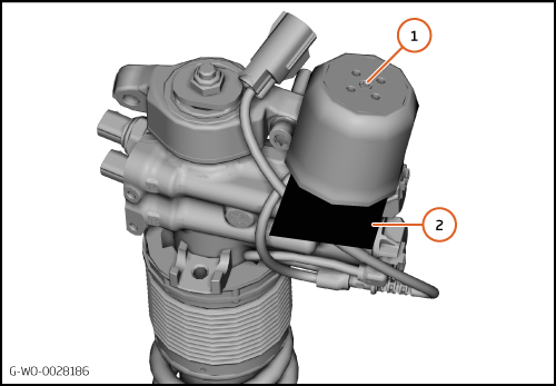
| | | 2. | A membrane type accumulator is shown (1).
A new metal bellows type accumulator is shown (2).
| | | | | Care Point: | The suspension system must be depressurised before you do the work that follows.
|
| | | 3. | Connect the McLaren Diagnostic System (MDS).
| | | | | | | 4. | Go to sequences in the Chassis Control Unit (CCU).
| | | 5. | Go to APMU maintenance mode.
| | | 6. | Do the Discharge Hydraulic System sequence.
| | | 
|
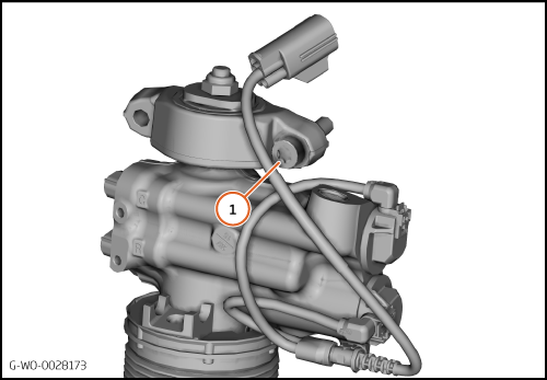
| | | Care Point: | Before you disconnect the electrical connectors, record their location.
|
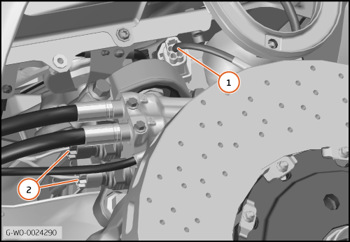
| | | 7. | Disconnect the electrical connector (1).
Disconnect the electrical connectors (2).
| | | 
|
| | | Care Point: | The step that follows is only applicable if nose lift is installed.
|
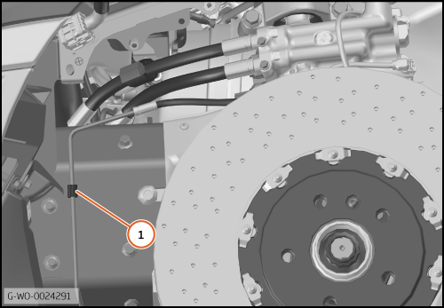
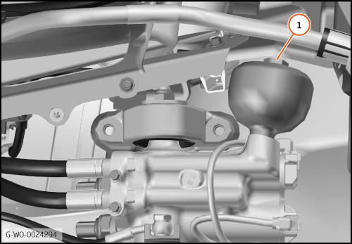
| | | 8. | Disengage the nose lift pipe from the clip (1).
| | | 
|
| | | Care Point: | You must have the aid of one/two more person/people for that step that follows.
|
| Care Point: | Use a lever to pull the lower wishbone down when you remove the bolts.
|
| Care Point: | Do not cause damage to parts when you remove the bolts.
|
| | | 9. | | | | 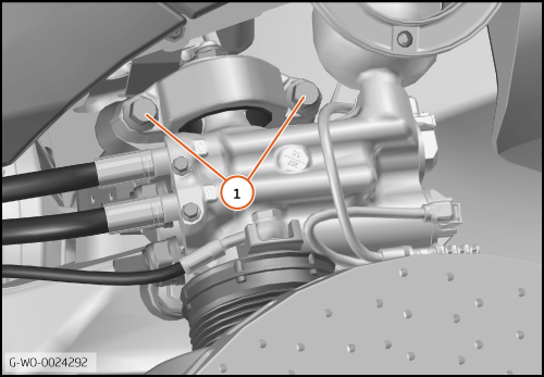
|
| 10. | Move the actuator outboard (1).
| | | 
|
| | | Care Point: | Do the step that follows if a membrane type accumulator is installed.
|
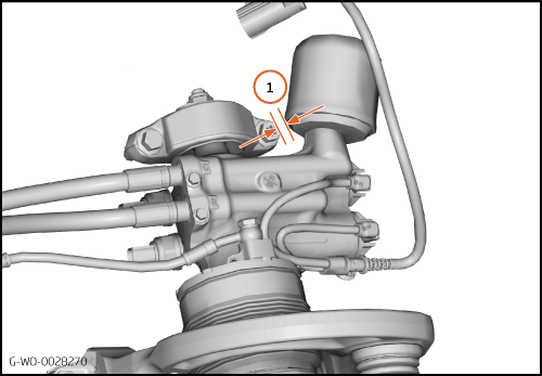
| | | 11. | Remove the membrane type accumulator (1) 25 Nm.
| | | 
|
| | | Care Point: | Do the step that follows if a metal bellows type accumulator is installed.
|
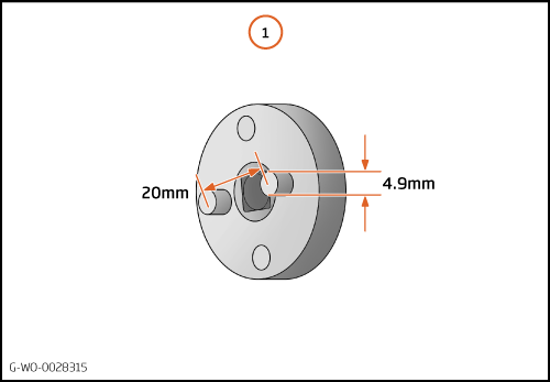
| Care Point: | You must use an applicable tool to remove the accumulator. Use a tool with a 3/8" square drive.
|
| | | 12. | Use a tool with two 4.9mm pins on a Pitch Circle Diameter (PCD) of 20mm (1).
| | | 13. | Remove the metal bellows type accumulator 40 Nm.
| | | 
|
Install Metal bellows type accumulator - Front
| | | Care Point: | Always replace the actuator bolts. Refer to the Spare Parts Catalogue (SPC) for part numbers.
|
| Care Point: | You must use the new clearance bolt at the rear of the actuator mount. Refer to the SPC for part numbers.
|
| Care Point: | For metal bellow type accumulators, if you follow the procedure below to replace the accumulator(s) a suspension bleed is not necessary.
|
| Care Point: | For membrane type accumulators, a suspension bleed is not necessary unless the actuator is replaced.
|
| | | 1. | Put the new clearance bolt (1) into the hole.
| | | | | Care Point: | You must make sure that there is no air in the accumulator after you do the step that follows.
|
| | | 2. | Carefully fill the new metal bellows type accumulator. Use Pentosin CHF202.
| | | 
|
| | | Care Point: | You must do the steps that follow to make sure that all of the fluid stays in the accumulator.
|
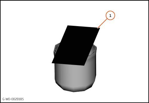
| Care Point: | Make sure that the accumulator is full with fluid.
|
| | | 3. | Put a plastic card (1) on the accumulator.
Make sure that the plastic card covers the hole on the accumulator.
| | | 
|
| | | Care Point: | You must have the aid of one/two more person/people for that step that follows.
|
| Care Point: | You must prevent the fluid spilling when you do the step that follows.
|
| | | 4. | Put the accumulator (1) together with the plastic card (2) into position on the actuator.
Remove the plastic card quickly and install the accumulator with your hand.
| | | 5. | Torque the accumulator 40 Nm.
| | | 
|
| | | Care Point: | You must have the aid of one/two more person/people for that step that follows.
|
| Care Point: | Use a lever to pull the lower wishbone down when you install the bolts.
|
| Care Point: | Do not cause damage to parts when you install the bolts.
|
| Care Point: | Tighten the bolts gradually and evenly.
|
| | | 6. | | | | 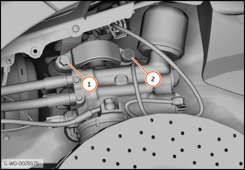
|
| 7. | The clearance (1) between the top mount bolt and the accumulator must be a minimum of 3mm.
| | | 
|
| | | Care Point: | Only do the step that follows if the clearance is less than 3mm.
|
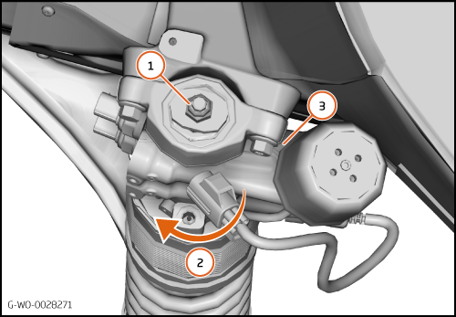
| | | 8. | If the clearance between the top mount bolt and the accumulator is less than 3mm, you must adjust the actuator.
Loosen the top mount nut (1).
Turn the actuator in the direction shown (2).
When the clearance (3) is a minimum of 3mm, tighten the top mount nut 45 Nm.
| | | 
|
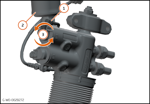
| 9. | Make sure that the electrical connector and wire (1) does not touch the accumulator (2).
Turn the electrical connector (3) in the direction shown if it is necessary.
| | | 10. | Clean the remaining hydraulic fluid from the accumulator and the actuator.
| | | 11. | Connect the McLaren Diagnostic System (MDS).
| | | 12. | Update the software for the metal bellows type accumulators if it is applicable. Refer to the table in the removal procedure.
| | | | | | | 13. | Go to sequences in the Chassis Control Unit (CCU).
| | | 14. | Do the Suspension Pressure Sensor Calibration procedure.
| | | 15. | Go to APMU Maintenance Mode.
| | | 16. | Do the Charge Hydraulic System sequence.
| | | 17. | Examine the suspension system for leaks.
| | | 18. | Install the remaining components in reverse order.
| | | 19. | Do a Diagnostic Trouble Code (DTC) read and clear.
| | | 
|