| |
| Care Point: | There are two bush types available and they are similar in appearance. Keep the new bushes separate in their package until you are ready to install them.
|
| Care Point: | The new wishbone bush part number: 14BA255CP is identified by a yellow paint pen mark.
The new wishbone bush part number: 14BA246CP is identified by a green paint pen mark.
|
| Care Point: | The bushes can only be replaced one time. When you reach the maximum limit, the wishbone must be replaced. Refer to the Spare Parts Catalogue (SPC) for part numbers.
|
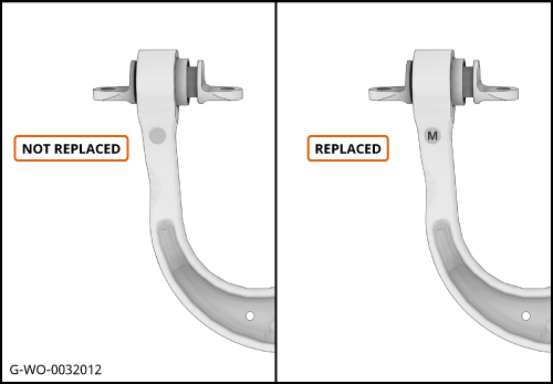
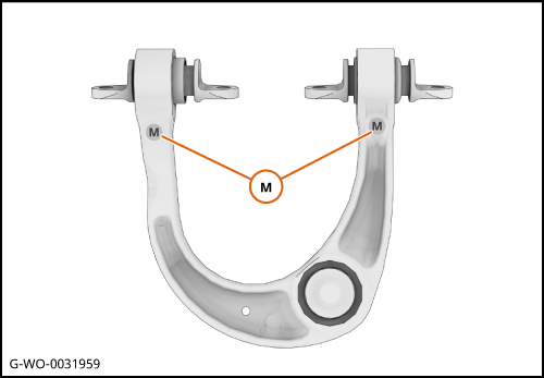
| Care Point: | If the bushes have been replaced there will be an identification mark (M) on the wishbone datum points upper face.
|
| | | 1. | Check if the bushes have been replaced.
| | | 
|
| | | Care Point: | Record the bush position. This will help you during the installation procedure to confirm correct fitment.
|
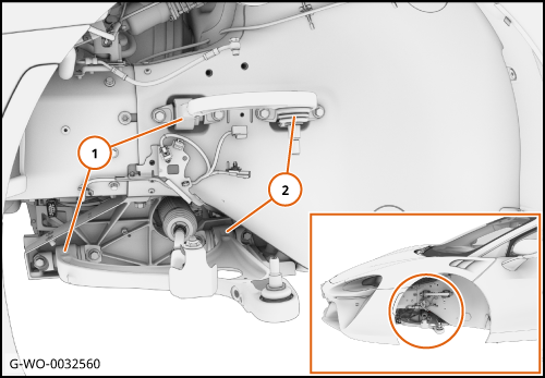
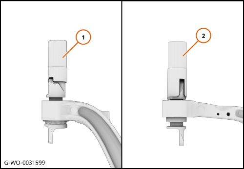
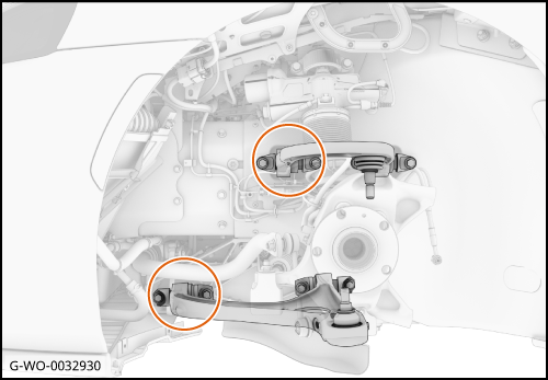
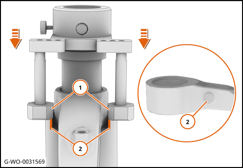
| | | 2. | The illustration shows the front bush (1) and the rear bush (2) position and the same principle applies to each corner of the vehicle.
| | | | | Care Point: | The procedure is an overview of how to use the bush remove/install tool.
|
| Care Point: | The wishbone must be removed to replace the bushes. Add the wishbone labour time to this repair to get the total labour time.
|
| | | 3. | Remove the wishbone.
| | | 
|
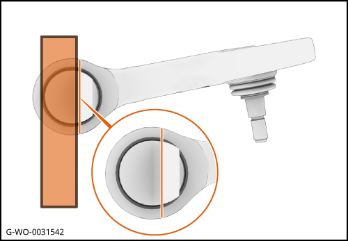
| | | Care Point: | Record the bush angle. This will help you during the installation procedure to confirm correct fitment.
|
| | | 4. | Use a straight edge to apply a timing mark across both sides of the wishbone casting.
| | | 
|
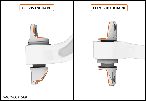
| | | Care Point: | Record the clevis position. This will help you during the installation procedure to confirm correct installation.
|
| | | 5. | Make a note of the clevis position.
| | | 
|
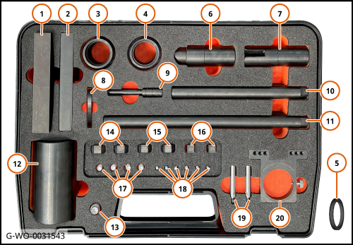
| 6. | The illustration and table shows the wishbone bush remove/install tools.
Tool number
| Tool Description
| Tool number
| Tool Description
|
1
| Press Frame With Hole
| 11
| Press Frame Bars Long
| 2
| Press Frame Without Hole
| 12
| Receiver Cup
| 3
| Bushing Tool A
| 13
| Identification Marker Punch
| 4
| Bushing Tool B
| 14
| 37, 38, 46, 53mm Arm Block
| 5
| Bushing Tool C
| 15
| 32, 33, 35, 36mm Arm Block
| 6
| Bushing Press Die A
| 16
| 23, 25, 28, 29 Arm Block
| 7
| Bushing Press Die B
| 17
| Press Frame Bolts M8x20mm
| 8
| Circlip
| 18
| Arm Block Bolts M4x16mm
| 9
| Bushing Pin
| 19
| Arm Block Legs
| 10
| Press Frame Bars Short
| 20
| Angle Plate
|
| | | 
|
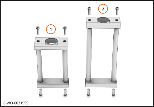
| 7. | The illustration shows the short press frame (1) and the long press frame (2).
The press frames are used to press out the bushes.
The press frames are used to support the wishbone.
| | | 
|
| 8. | The illustration shows the bushing press die tools.
Bushing press die A (1).
Bushing press die B (2).
| | | 
|
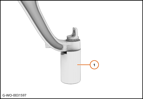
| 9. | The illustration shows the receiver cup (1) used to support the wishbone.
| | | 
|
| | | Care Point: | The wishbone bushes are replaced as a pair. Refer to SPC for part numbers.
|
| Care Point: | The use of a hydraulic press is required to remove the bushes.
|
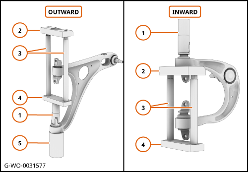
| Care Point: | The illustration shows examples of how the suspension bush replacement tool is used.
|
| | | 10. | Position the press die (1) onto the bush.
Use the press frame (2)(3)(4) and receiver cup (5) to remove the bush.
| | | 
|
| |
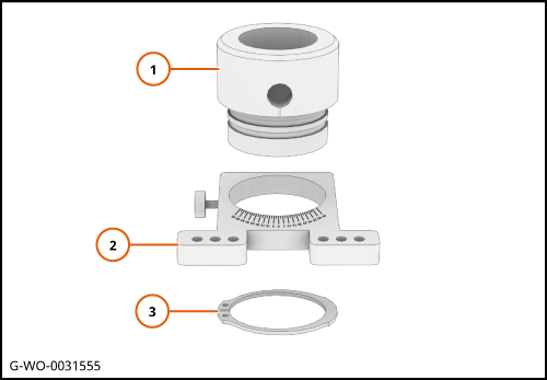
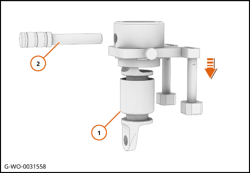
| | | 1. | Install the bushing press tool (1) into the angle plate (2).
Install the circlip (3) into the groove.
| | | 
|
| |
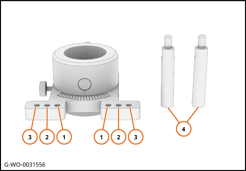
| | | 2. | Install the arm block legs (4) in position (1),(2) or (3) and tighten.
| | | 
|
| |
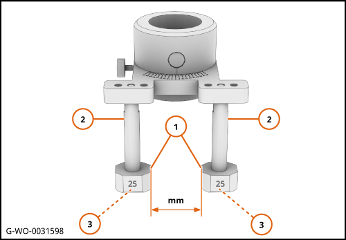
| Care Point: | Make sure that the arm blocks (1) are installed parallel to each other.
|
| | | 3. | Install the arm blocks (1) on to the arm block legs (2).
Put the required arm block size (mm) on the inner face.
Install the arm block bolts (3) and tighten.
| | | 
|
| 4. | The illustration shows the clevis position options.
| | |
|
| |
| Care Point: | Make sure that the radius (1) on the bush is positioned at the bottom.
|
| | | 5. | Put the bushing press tool over the bush.
Insert the bushing pin (2) into the hole to hold the bush in position.
| | | 
|
| |
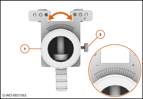
| | | 6. | Set the bushing press tool angle by turning the bushing press tool (1) to the specified angle.
Tighten the lock screw (2) once the angle is set.
| | | 
|
| | | Care Point: | The step that follows is only applicable to the P22 (GT) front bushes associated with the front upper and lower wishbones.
|
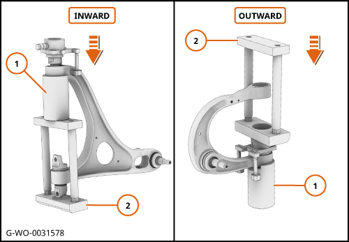
| | | 7. | The tool C is required for the front bush only in the location shown on both sides of the vehicle.
| | | 
|
| | | Care Point: | The step that follows is only applicable to the P22 (GT) front bushes associated with the front upper and lower wishbones.
|
| | | 8. | Position the bushing tool C (1) on to the wishbone casting.
Make sure that the arm blocks (2) are positioned in line with the wishbone datum points (3).
| | | 
|
| |
| | | 9. | Make sure that the arm blocks (1) are positioned in line with the wishbone datum points (2).
| | | 
|
| | | Care Point: | The use of a hydraulic press is required to install the bushes.
|
| | | 10. | Use the receiver cup (1) and the press frame (2) with the bushing press tool to install the bushes.
| | | 
|
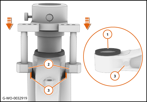
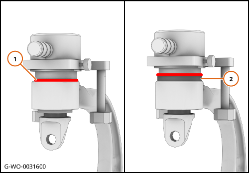
| | | Care Point: | The bush is in the correct installation position when the tool has made contact with the wishbone (1).
|
| Care Point: | The P22 (GT) upper and lower front bushes are in the correct position when the bushing tool A/B has made contact with the bushing tool C (2).
|
| | | 11. | Check that the bushing press tool has made contact in the area shown.
| | | 
|
| 12. | Check that the new bushes are aligned with the timing mark.
| | |
|
| | | Care Point: | You must use the punch provided to put an identification mark (M) on to the bush upper datum points.
|
| | | 13. | Put an identification mark on the wishbone to indicate that the bushes have been replaced.
| | | 14. | Install the components in reverse order.
| | | | | Care Point: | The procedure below must be claimed separately if you make a warranty claim.
|
| | | 15. | Make sure that the suspension geometry is in tolerance.
| | | 
|