| 1. | Do the steps that follow for any incorrect valve clearances.
| | |
|
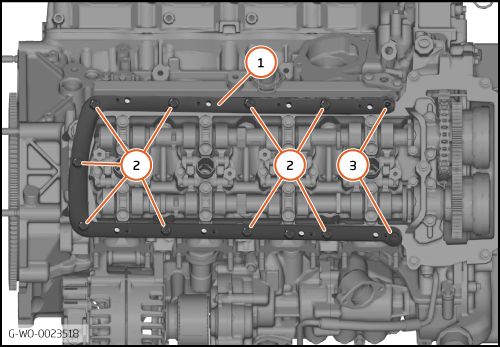
| 2. | | | | 3. | | | | 4. | Tighten the bolts (3) 7 Nm.
| | | 
|
| | | Care Point: | Install the main body to the applicable pair of valves.
|
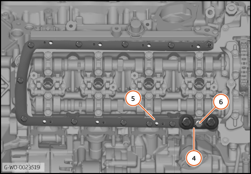
| | | 5. | | | | 6. | Tighten the bolt (6) 15 Nm.
| | | 
|
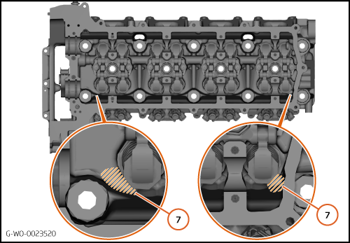
| | | Care Point: | Make sure that unwanted objects do not go into the oil galleries.
|
| | | 7. | Install plugs to make sure that unwanted objects do not go into the oil galleries (7).
| | | 
|
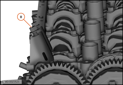
| | | Care Point: | Make sure the plunger is seated correctly on the valve cap.
|
| Care Point: | Only compress the valve spring sufficiently to remove the valve shim. The valve can touch the piston.
|
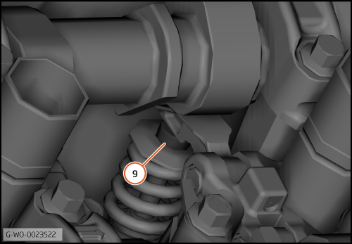
| | | 8. | Turn the bolt (8) clockwise to compress the valve spring.
| | | 
|
| 9. | Remove the valve shim (9).
| | | 
|
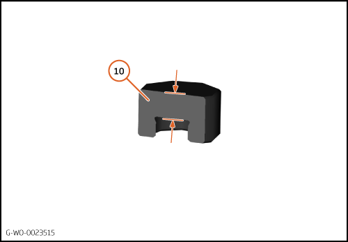
| 10. | Use a micrometer to measure the thickness of the valve shim that you have removed (10).
| | | | | Care Point: | A clearance of 0.170 to 0.200 is permitted for the exhaust valves.
|
| Care Point: | A clearance of 0.120 to 0.150 is permitted for the inlet valves.
|
| Care Point: | Use the clearances that you recorded earlier.
|
| | | 11. | Calculate the thickness of the shim that is necessary to get the correct clearance.
| | | | | Care Point: | Visually examine the collets to make sure they are installed correctly.
|
| | | 12. | Insert the correct shim.
| | | 
|
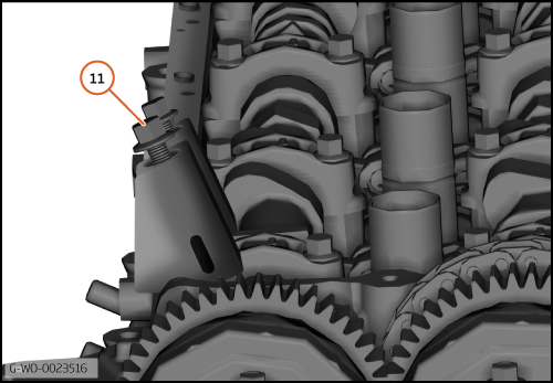
| 13. | Turn the bolt (11) counterclockwise to decompress the valve spring.
| | | 14. | Do the procedure for each valve clearance that is not in tolerance.
| | | 
|
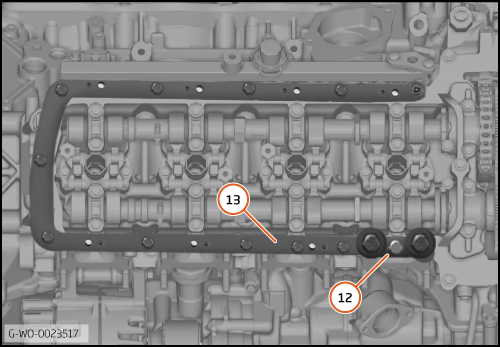
| 15. | Remove the main body (12) from the mount rail (13).
| | | 16. | Turn the crankshaft clockwise through three complete turns.
| | | | | Care Point: | Make sure that the camshafts are in the positions specified in steps 1 and 2 when you measure valve clearances.
|
| | | 17. | Measure the valve clearances again.
| | | | | Care Point: | All valve clearances must be in the specified range.
|
| | | 18. | If any valve clearances are incorrect, you must go back to step 1 and install the necessary valve shims.
| | | | | Care Point: | Only do this step after you have confirmed that each valve clearance is in the specified range.
|
| | | 19. | Remove the main body from the mount rail.
| | | 20. | Remove the mount rail from the cylinder head.
| | | 
|